Appendix
Appendix A – I2C Report ID Definition
| Bit (0 ~ 3) | Main class for Report ID | Bit (4 ~ 7) | Extend class for Data Format | ||
|---|---|---|---|---|---|
| value | binary | Description | value | binary | Description |
| 0x1 | 0000 | General Touch Data | 0x8 | 1000 | Touch + Scan time |
| 0x4 | 0100 | Function Key | 0x9 | 1001 | Touch + Area (Width, Height) + Scan time |
| 0x1 | 0001 | General Touch Data | 0xc | 1100 | Touch + Pressure + Scan time |
| 0xd | 1101 | Touch + Area (Width, Height) + Pressure + Scan time | |||
| Report ID | Length |
|---|---|
| 0x21 | 64 * 1 |
| 0x25 | 64 * 5 |
| 0x29 | 64 * 9 |
| 0x2d | 64 * 13 |
| B0 | B1 | B2 | B3 | B4 | B5 | B6 | B7 | B8 | B9 | B10 | B11 | B12 | B13 | B14 | B15 | B16 | B17 | ... | ... | Bxx | ... | ... | ... | ... | ... | B63 | ||
|---|---|---|---|---|---|---|---|---|---|---|---|---|---|---|---|---|---|---|---|---|---|---|---|---|---|---|---|---|
| 0x24 | 0x00 | 0x81 | S1 | ID1 | X1 | X1 | Y1 | Y1 | S2 | ID2 | X2 | X2 | Y2 | Y2 | ... | ... | ... | ... | ... | ... | ... | Y5 | Cnt | Time | Time | |||
| 0x24 | 0x00 | 0x81 | S6 | ID6 | X6 | X6 | Y6 | Y6 | S7 | ID7 | X7 | X7 | Y7 | Y7 | ... | ... | ... | ... | ... | ... | ... | Y10 | Cnt | Time | Time | |||
| 0x38 | 0x00 | 0x91 | S1 | ID1 | X1 | X1 | Y1 | Y1 | W1 | W1 | H1 | H1 | S2 | ID2 | X2 | X2 | Y2 | Y2 | W2 | W2 | ... | H5 | Cnt | Time | Time | |||
| 0x38 | 0x00 | 0x91 | S6 | ID6 | X6 | X6 | Y6 | Y6 | W6 | W6 | H6 | H6 | S7 | ID7 | X7 | X7 | Y7 | Y7 | W7 | W7 | ... | H10 | Cnt | Time | Time | |||
| 0x29 | 0x00 | 0xc1 | S1 | ID1 | X1 | X1 | Y1 | Y1 | P1 | S2 | ID2X2 | X2 | Y2 | Y2 | P2 | ... | ... | ... | ... | ... | ... | P5 | Cnt | Time | Time | |||
| 0x29 | 0x00 | 0xc1 | S6 | ID6 | X6 | X6 | Y6 | Y6 | P6 | S7 | ID7X7 | X7 | Y7 | Y7 | P7 | ... | ... | ... | ... | ... | ... | P10 | Cnt | Time | Time | |||
| 0x3D | 0x00 | 0xd1 | S1 | ID1 | X1 | X1 | Y1 | Y1 | P1 | W1 | W1 | H1 | H1 | S2 | ID2 | X2 | X2 | Y2 | Y2 | P2 | ... | H5 | Cnt | Time | Time | |||
| 0x3D | 0x00 | 0xd1 | S6 | ID6 | X6 | X6 | Y6 | Y6 | P6 | W6 | W6 | H6 | H6 | S7 | ID7 | X7 | X7 | Y7 | Y7 | P7 | ... | H10 | Cnt | Time | Time | |||
| 0x24 | 0x00 | 0x04 | S1 | ID1 | X1 | X1 | Y1 | Y1 | S2 | ID2 | X2 | X2 | Y2 | Y2 | ... | ... | ... | ... | ... | ... | Y5 | Cnt | FK | FK | ||||
| 0x24 | 0x00 | 0x04 | S6 | ID6 | X6 | X6 | Y6 | Y6 | S7 | ID7 | X7 | X7 | Y7 | Y7 | ... | ... | ... | ... | ... | ... | Y10 | Cnt | FK | FK | ||||
| 0x38 | 0x00 | 0x14 | S1 | ID1 | X1 | X1 | Y1 | Y1 | W1 | W1 | H1 | H1 | S2 | ID2 | X2 | X2 | Y2 | Y2 | W2 | W2 | .. | H5 | Cnt | FK | FK | |||
| 0x38 | 0x00 | 0x14 | S6 | ID6 | X6 | X6 | Y6 | Y6 | W6 | W6 | H6 | H6 | S7 | ID7 | X7 | X7 | Y7 | Y7 | W7 | W7 | ... | H10 | Cnt | FK | FK | |||
| 0x29 | 0x00 | 0x44 | S1 | ID1 | X1 | X1 | Y1 | Y1 | P1 | S2 | ID2X2 | X2 | Y2 | Y2 | P2 | ... | ... | ... | ... | ... | P5 | Cnt | FK | FK | ||||
| 0x29 | 0x00 | 0x44 | S6 | ID6 | X6 | X6 | Y6 | Y6 | P6 | S7 | ID7X7 | X7 | Y7 | Y7 | P7 | ... | ... | ... | ... | ... | P10 | Cnt | FK | FK | ||||
| 0x3D | 0x00 | 0x54 | S1 | ID1 | X1 | X1 | Y1 | Y1 | P1 | W1 | W1 | H1 | H1 | ID2 | S2 | X2 | X2 | Y2 | Y2 | P2 | ... | H5 | Cnt | FK | FK | |||
| 0x3D | 0x00 | 0x54 | S6 | ID6 | X6 | X6 | Y6 | Y6 | P6 | W6 | W6 | H6 | H6 | ID7 | S7 | X7 | X7 | Y7 | Y7 | P7 | ... | H10 | Cnt | FK | FK | |||
| 0x26 | 0x00 | 0x84 | S1 | ID1 | X1 | X1 | Y1 | Y1 | S2 | ID2 | X2 | X2 | Y2 | Y2 | ... | ... | ... | ... | ... | ... | Y5 | Cnt | Time | Time | FK | FK | ||
| 0x26 | 0x00 | 0x84 | S6 | ID6 | X6 | X6 | Y6 | Y6 | S7 | ID7 | X7 | X7 | Y7 | Y7 | ... | ... | ... | ... | ... | ... | Y10 | Cnt | Time | Time | FK | FK | ||
| 0x3A | 0x00 | 0x94 | S1 | ID1 | X1 | X1 | Y1 | Y1 | W1 | W1 | H1 | H1 | S2 | ID2 | X2 | X2 | Y2 | Y2 | W2 | W2 | ... | H5 | Cnt | Time | Time | FK | FK | |
| 0x3A | 0x00 | 0x94 | S6 | ID6 | X6 | X6 | Y6 | Y6 | W6 | W6 | H6 | H6 | S7 | ID7 | X7 | X7 | Y7 | Y7 | W7 | W7 | ... | H10 | Cnt | Time | Time | FK | FK | |
| 0x2B | 0x00 | 0xc4 | S1 | ID1 | X1 | X1 | Y1 | Y1 | P1 | S2 | ID2 | X2 | X2 | Y2 | Y2 | P2 | ... | ... | ... | ... | P5 | Cnt | Time | Time | FK | FK | ||
| 0x2B | 0x00 | 0xc4 | S6 | ID6 | X6 | X6 | Y6 | Y6 | P6 | S7 | ID7 | X7 | X7 | Y7 | Y7 | P7 | ... | ... | ... | ... | P10 | Cnt | Time | Time | FK | FK | ||
| 0x3F | 0x00 | 0xd4 | S1 | ID1 | X1 | X1 | Y1 | Y1 | P1 | W1 | W1 | H1 | H1 | S2 | ID2 | X2 | X2 | Y2 | Y2 | P2 | ... | H5 | Cnt | Time | Time | FK | FK | |
| 0x3F | 0x00 | 0xd4 | S6 | ID6 | X6 | X6 | Y6 | Y6 | P6 | W6 | W6 | H6 | H6 | S7 | ID7 | X7 | X7 | Y7 | Y7 | P7 | ... | H10 | Cnt | Time | Time | FK | FK |
Introduction
This is SiS95xx touch controller programming guide. SiS touch controller communicates with the host via standard I2C interface. For specific configuration command, please refer to Chapter 2. There will bring more details.
Interface
There will introduce I2C related and the instructions of each command.
I2C Related
SiS95xx provided a full range of touch controllers for an optimum performance solution of the capacitive touch panels. The host platform can communicate with the controllers via I2C, SPI, RS232, or USB port. This section focuses on the I2C port. For I2C driver developer and relative touch software on the host platform side (the Master), this section provides the format of I2C transactions with the firmware of the controller (the Slave), and the necessary flexibility on the touch position for adjusting.
I/O Pin Definitions
| Pin Number | Pin Name | Pin Attribute | Description |
|---|---|---|---|
| 1 | VDD | PWR | 3.3V |
| 2 | I2C_CLK | In/Out | I2C Clock |
| 3 | I2C_DA | In/Out | I2C Data |
| 4 | INT | Out | Interrupt Pin |
| 5 | RESET# | In | External reset. Active low. |
| 6 | GND | PWR | Ground |
**Power On/Reset Sequence**


**I2C Power-On Sequence**

| Description | Min | Max | Unit |
|---|---|---|---|
| Rise time from 0.1*VDD to 0.9*VDD | - | 2 | ms |
| Reset pulse width | 10 | - | us |
| From VDD stable at 3.3V to RESET# reach at 2V | 5 | - | ms |
| Time of starting to report point after Reset# reach at 3.3V | 100 | - | ms |
**I2C AC Waveform**
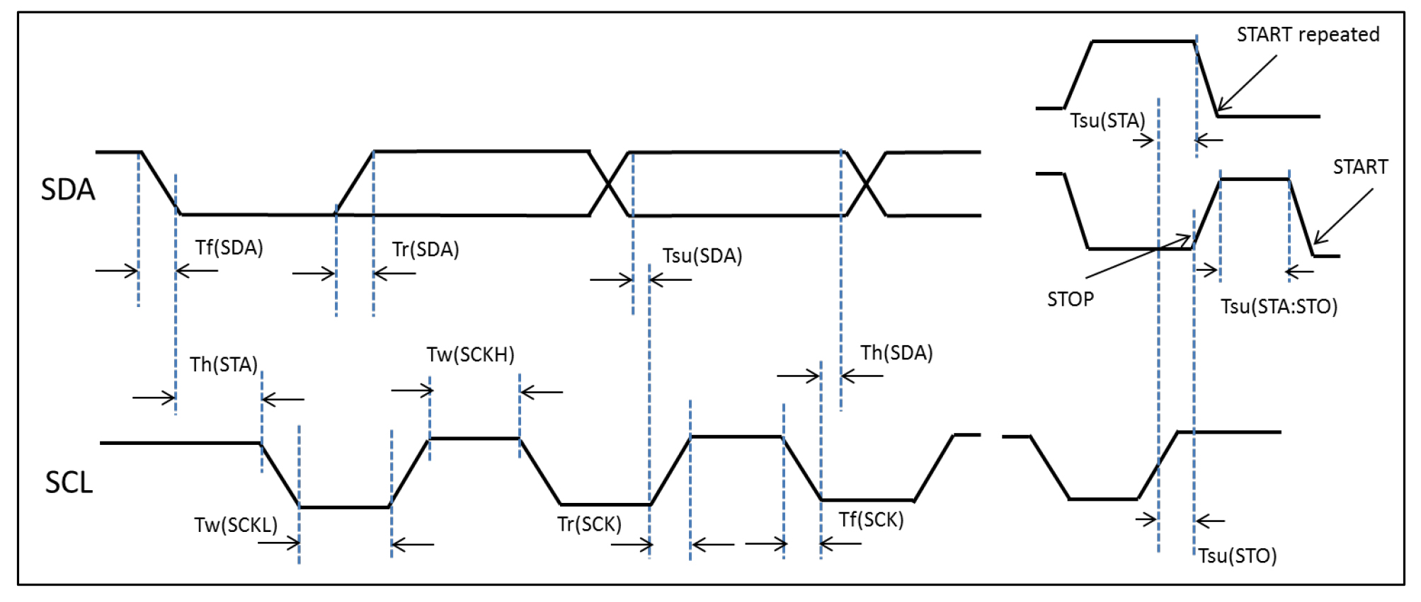
| Symbol | Parameter | SCL=100KHz | SCL=400KHz | Unit | ||
|---|---|---|---|---|---|---|
| Min | Max | Min | Max | |||
| Tw(SCLH) | SCL clock high time | 4.7 | 1.3 | us | ||
| Tw(SCLL) | SCL clock low time | 4.0 | 0.6 | |||
| Tsu(SDA) | SDA setup time | 250 | 100 | ns | ||
| Th(SDA) | SDA data hold time | 0 | 0 | 900 | ||
| Tr(SDA) Tr(SCL) | SDA&SCL rise time | 1000 | 300 | |||
| Tf(SDA) Tf(SCL) | SDA&SCLA fall time | 300 | 300 | |||
| Th(STA) | Start condition hold time | 4.0 | 0.6 | us | ||
| Tsu(STA) | Repeated Start condition setup time | 4.7 | 9.6 | |||
| Tsu(STO) | Stop condition setup time | 4.0 | 0.6 | |||
| Tw(STO:STA) | Stop to Start condition time(bus free) | 4.7 | 1.3 | |||
**I2C ACPI Setting**
| Vendor | SiS |
| Slave Address | 0x5c(7-bits addressing, programmable) |
| Clock rate | @400 kHz (fast mode) |
| Interrupt mode | Default active low, level trigger |
| _CID | PNP0C50 |
| _DSM | 3CDFF6F7-4267-4555-AD05-B30A3D8938DE |
| HID Descriptor address | 0x0000 |
### I2C BUS Protocol Each I2C transaction transfers one I2C packet data. The INT pin is low level trigger. Touch device controller will pull INT pin low until all data was stored in the controller buffer or all controller buffer data was received by host.
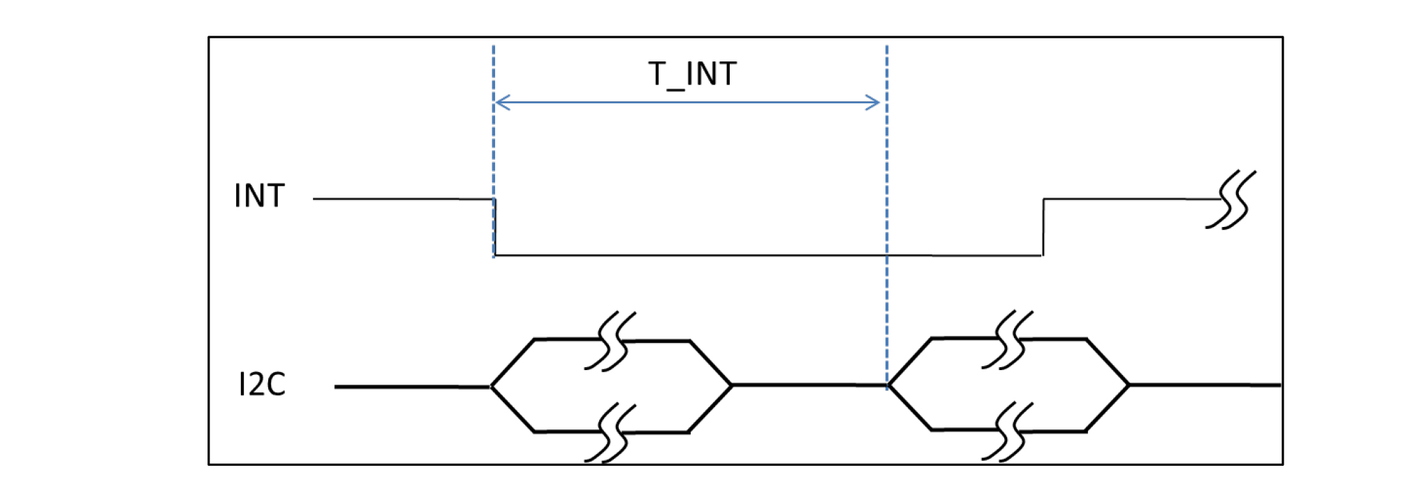
#### I2C Touch Protocol Each touch packet is maximum 64 bytes. Normally, there are 2 packets in one touch package. Host needs to read the package for input report retrieval. Each touch packet contains 2 bytes ”Length” and maximum 62 bytes data payload. The value of “Length” is calculated by 2 bytes for “Length” field and N bytes for valid input data in the payload

**Annotation** Gray block: From Host to Device White block: From Device to Host Address : 7 bits, touch device slave address (default 0x5C) S: Start Condition Length: PAYLAD length P: Stop Condition R: Host Read, bit 0 DATA: Input Data
#### I2C Touch Package Format The HID over I2C touch packet format is fixed length which depends on Report ID. While the touch event is happening, each touch packet will have maximum 5 touch data. If actual touch data is less than 5, the rest of touch data should be set zero in each touch packet for keeping the fixed length. There is no Cyclic Redundancy Check (CRC) in the HID over I2C touch packet format. 1st packet sends touch data from touch data0 to touch data4 with total touch count number in this touch package. 2nd package sends touch data from touch data5 to touch data9. 1st package
| 2 Bytes | 1 Byte | 4-9 Bytes | … | 6 Bytes | 1 Byte | 2 Bytes |
|---|---|---|---|---|---|---|
| Length Field | Report ID | Touch Data() | … | Touch Data4 | Touch CNT | Scan Time |
2st package
| 2 Bytes | 1 Byte | 6 Bytes | … | 6 Bytes | 1 Byte | 2 Bytes |
|---|---|---|---|---|---|---|
| Length Field | Report ID | Touch Data5 | … | Touch Data9 | Touch CNT = 0 | Scan Time |
**Touch Data format** Take general 𝐼2C touch packet for example. General 𝑰𝟐𝐂 Touch Package Format
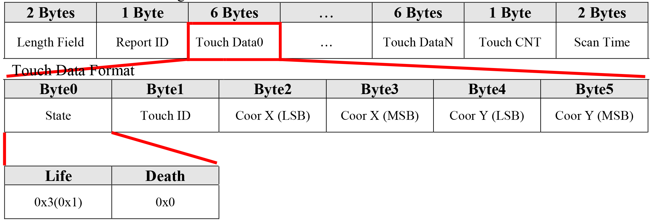
- Life: Report touch event - Death: Don’t report touch event. Take Customized 𝐼2C touch packet for example Customized 𝐼2C Touch Packet Format
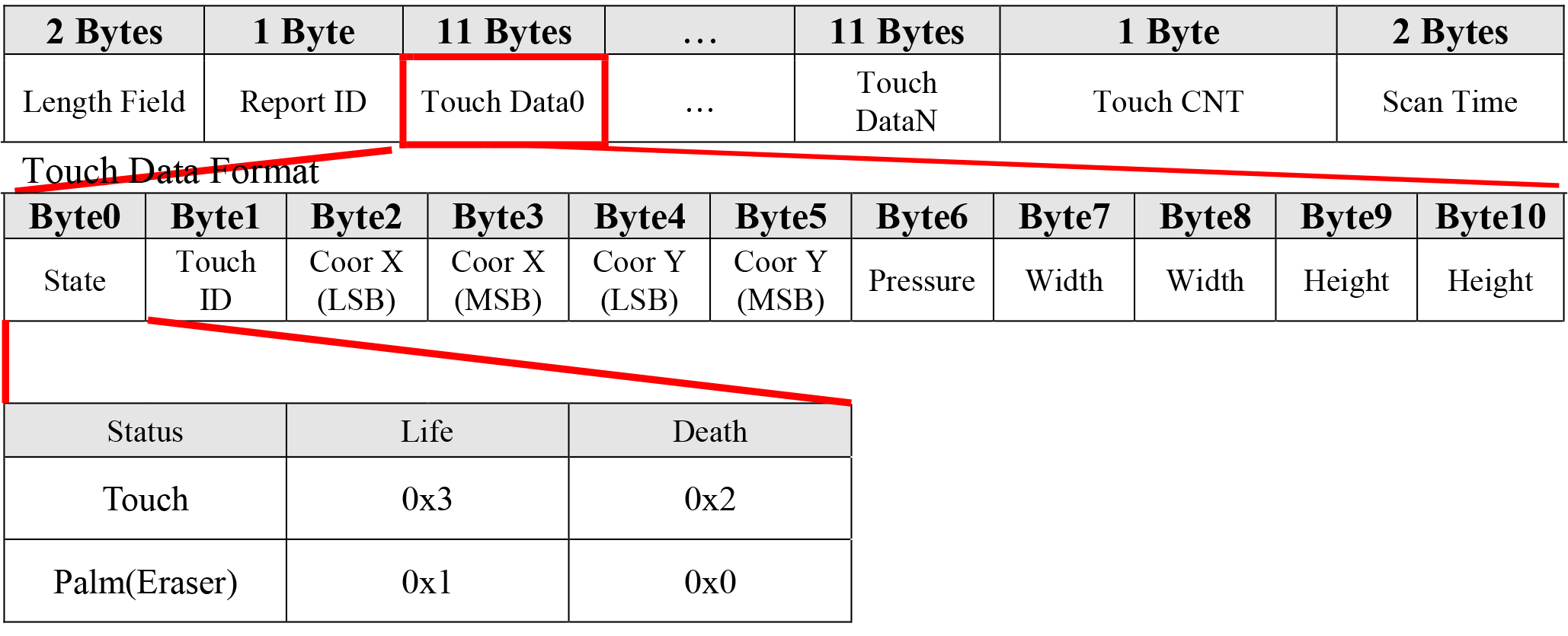
- Customer application can get Palm or Eraser data format while the byte0 status is 0x1 and can be set it as Palm/Eraser function if needed by the application. Report ID Definition please refers to Appendix A. HID over I2C Touch Format Table please refer to Appendix B.
I2C Command Protocol
Command Protocol
- Host Write - Host sends an output report to device for specific requests. The output report sending from host is maximum 64 Bytes, which includes 2 Bytes output register, 2 Bytes length field, and payload data.
- Host Read - Device needs to parse the output report and then transmit the input report to host for response.
Host Write (Output Report)

**Annotation:** Gray block: From Host to Device White block: From Device to Host S: Start Condition Length: DATA length P: Stop Condition W: Write Host Read (Input Report)

**Annotation:** Gray block: From Host to Device S: Start Condition P: Stop Condition White block: From Device to Host Length: DATA length R: Read **Command Package Format** Hardware write: Host to Device
| 2 Bytes | 2 Bytes | 1 Byte | 1 Byte | 1 Byte | 1 Byte | 56 Bytes |
|---|---|---|---|---|---|---|
| Out Register | Length Field | Report ID | Reserved | CMD | CRC | Payload |
**Command Package Format** Hardware read: Device to Host
| Byte num | 2 Bytes | 2 Bytes | 1 Byte | 1 Byte | 1 Byte | 1 Byte | 56 Bytes | |
|---|---|---|---|---|---|---|---|---|
| Device to Host | Length Field | Report ID | CRC16 | ACK / NACK | Status | Payload | ||
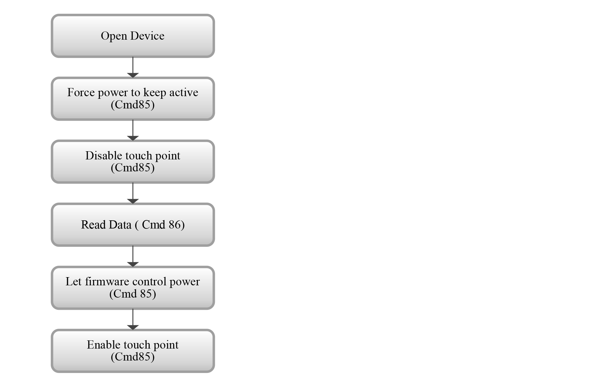
### I2C CMD There are I2C command lists.
| CMD | CMD Name | Description |
|---|---|---|
| 0x86 | Read Data CMD | This command is used when the host wants to read the device data from a certain physical/virtual address (a3a2a1a0) with ReadLength (bytes). |
| 0x85 | Change Mode CMD | This command is used for changing the device control mode by Type and Mode. |
I2C Format
| Type | Byte0 | Byte1 | Byte2 | Byte3 | Byte4 | Byte5 | Byte6 | Byte7 | ByteB8~B63 |
|---|---|---|---|---|---|---|---|---|---|
| OUT (Command Report) | Output Register | Length field LSB/MSB | Report ID (Appendix A) | Reserved (0x0) | CMD | CRC 16 | PAYLOAD | ||

| Note: (Following above table) | |
|---|---|
| OUT | CRC 16 = CMD + PAYLOAD, Length = 2(Length) + 4(byte4~7) + PAYLOAD If it’s not through the Bridge Board, the Outer Register is 0x0004. Now we test through the Bridge Board, the Outer Register is 0x0140. |
| Touch Report | If define *attribute will be enabled. CRC 16 = Length field + Report ID + Finger Report + Touch Count + *Scan Time + *Function Key Output: byte0~byte3 and Input: bypte0~byte1 is filled by OS, not our business |
Finger Report Table:
| Finger Report (Byte3 ~ 8) | |||||
|---|---|---|---|---|---|
| State | Toucht ID | Coor X (LSB) | Coor X (MSB) | Coor Y (LSB) | Coor Y (MSB) |
#### I2C Response Format
| Type | Byte0 | Byte1 | Byte2 | Byte3 | Byte4 | Byte5 | Byte6 | Byte7 | B8~B63 | |
|---|---|---|---|---|---|---|---|---|---|---|
| ACK | IN | Length field (0x8) | Reserved | Report ID | CRC 16 | 0xEF | 0xBE | STATUS (Refer to STATUS table) | N/A | |
| NACK | IN | Length field (0x8) | Reserved | Report ID | CRC 16 | 0xAD | 0xDE | STATUS (Refer to STATUS table) | N/A | |
STATUS Table:
| Detect Device | Priority | Error Event | STATUS | |
|---|---|---|---|---|
| byte6(Master) | byte7(Slave) | |||
| Master | 0 | ALL Pass | 0x00 | 0x00 |
| 1 | CMD | 0x00 | 0x01 | |
| 2 | Length field | 0x00 | 0x02 | |
| 3 | CRC | 0x00 | 0x03 | |
| 4 | Address | 0x00 | 0x04 | |
| 5 | R/W Length | 0x00 | 0x05 | |
| 6 | Mode | 0x00 | 0x06 | |
| 7 | SPI Program Fail | 0x00 | 0x07 | |
| 8 | Report ID | 0x00 | 0x08 | |
| 9 | Reset Success | 0x00 | 0x9 | |
| 10 | Dev boot loader | 0x00 | 0x0a | |
| Slave | 1 | CMD | 0x01 | 0x01 |
| 2 | Length field | 0x01 | 0x02 | |
| 3 | CRC | 0x01 | 0x03 | |
| 4 | Address | 0x01 | 0x04 | |
| 5 | R/W Length | 0x01 | 0x05 | |
| 6 | Mode | 0x01 | 0x06 | |
| 7 | SPI Program Fail | 0x01 | 0x07 | |
| 8 | Report ID | 0x01 | 0x08 | |
| 9 | Reset Success | 0x01 | 0x09 | |
| 10 | Dev boot loader | 0x01 | 0x0a | |
#### I2C CMD Introduction - 0x86 CMD: Read Data CMD
| Type | Byte0 | Byte1 | Byte2 | Byte3 | Byte4 | Byte5 | Byte6 | Byte7 | B8~B11 | B12~B13 | B14~ |
|---|---|---|---|---|---|---|---|---|---|---|---|
| OUT | 0x04 | 0x00 | 0x0c | 0x00 | Report ID | 0x0 | 0x86 | CRC16 | a0~a3 | Read length LSB/MSB | N/A |
| IN | (0x8~ 0x3c) | 0x00 | Report ID | CRC 16 | ACK/NACK | STATUS | d0~d51 | ||||
| Type | Byte0 | Byte1 | Byte2 | Byte3 | Byte4 | Byte5 | Byte6 | Byte7 | Byte8 | Byte9 | Byte10~ |
|---|---|---|---|---|---|---|---|---|---|---|---|
| OUT | 0x04 | 0x00 | 0x08 | 0x00 | Report ID | 0x0 | 0x85 | CRC16 | Mode | Type | N/A |
| IN | 0x08 | 0x00 | Report ID | CRC 16 | ACK/NACK | STATUS | N/A | ||||
Cange Mode Table:
| Type | Mode | Type | Comment |
|---|---|---|---|
| Byte4 | Byte5 | ||
| ENABLE_DIAGNOSIS_MODE | 0x21 | 0x01 | Flow control |
| DISABLE_DIAGNOSIS_MODE | 0x20 | 0x01 | Flow control |
| PWR_CMD_FWCTRL | 0x50 | 0x09 | Power mode control |
| PWR_CMD_ACTIVE | 0x51 | 0x09 | Power mode control |
| Type | Byte0 | Byte1 | Byte2 | Byte3 | Byte4 | Byte5 | Byte6 | Byte7 | B8~B11 | B12~B13 | B14~ |
|---|---|---|---|---|---|---|---|---|---|---|---|
| OUT | 0x04 | 0x00 | 0x0c | 0x00 | 0x21 | 0x0 | 0x86 | CRC 16 | 0x52000000 | 0x4000 | N/A |
| In | (0x8~ 0x3c) | 0x00 | 0x21 | CRC 16 | 0xef | 0xbe | 0x0000 | d0~d51 | |||
| Type | Byte0 | Byte1 | Byte2 | Byte3 | Byte4 | Byte5 | Byte6 | Byte7 | Byte8 | Byte9 | Byte10~ |
|---|---|---|---|---|---|---|---|---|---|---|---|
| OUT | 0x04 | 0x00 | 0x08 | 0x00 | 0x21 | 0x0 | 0x85 | CRC 16 | 0x51 | 0x09 | N/A |
| In | 0x8 | 0x00 | 0x21 | CRC 16 | 0xef | 0xbe | 0x0000 | N/A | |||
| Type | Byte0 | Byte1 | Byte2 | Byte3 | Byte4 | Byte5 | Byte6 | Byte7 | Byte8 | Byte9 | Byte10~ |
|---|---|---|---|---|---|---|---|---|---|---|---|
| OUT | 0x04 | 0x00 | 0x08 | 0x00 | 0x21 | 0x0 | 0x85 | CRC 16 | 0x21 | 0x01 | N/A |
| In | 0x8 | 0x00 | 0x21 | CRC 16 | 0xef | 0xbe | 0x0000 | N/A | |||
| Type | Byte0 | Byte1 | Byte2 | Byte3 | Byte4 | Byte5 | Byte6 | Byte7 | Byte8 | Byte9 | Byte10~ |
|---|---|---|---|---|---|---|---|---|---|---|---|
| OUT | 0x04 | 0x00 | 0x08 | 0x00 | 0x21 | 0x0 | 0x85 | CRC 16 | 0x50 | 0x09 | N/A |
| In | 0x8 | 0x00 | 0x21 | CRC 16 | 0xef | 0xbe | 0x0000 | N/A | |||
| Type | Byte0 | Byte1 | Byte2 | Byte3 | Byte4 | Byte5 | Byte6 | Byte7 | Byte8 | Byte9 | Byte10~ |
|---|---|---|---|---|---|---|---|---|---|---|---|
| OUT | 0x04 | 0x00 | 0x08 | 0x00 | 0x21 | 0x0 | 0x85 | CRC 16 | 0x20 | 0x01 | N/A |
| In | 0x8 | 0x00 | 0x21 | CRC 16 | 0xef | 0xbe | 0x0000 | N/A | |||
