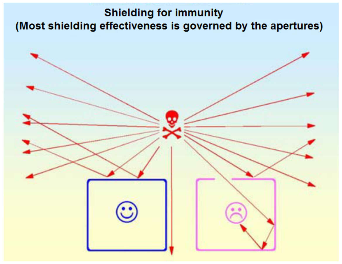
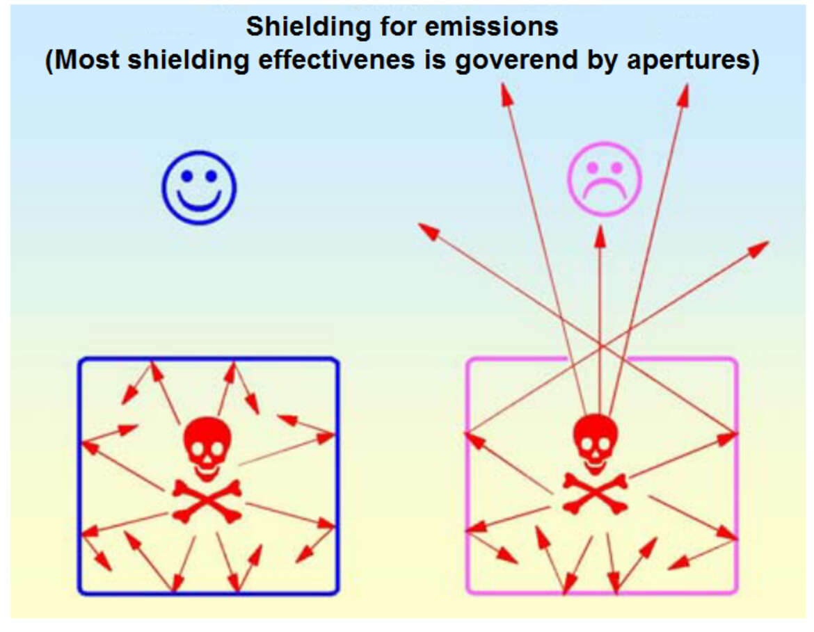
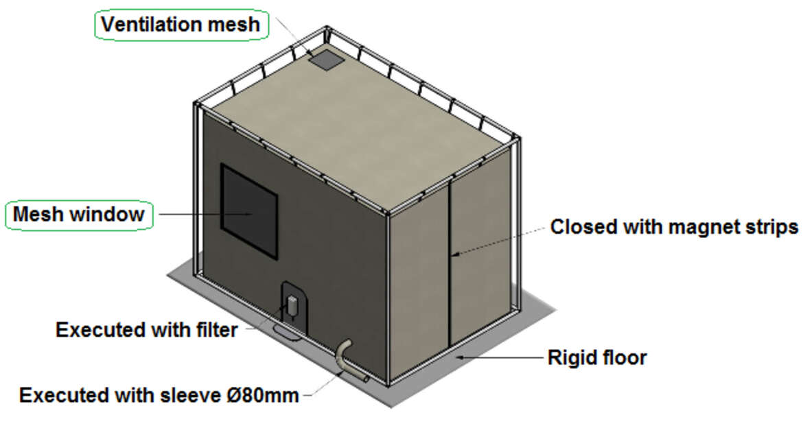
A shield puts an impedance (the effective resistance of an electric circuit or component to alternating current, arising from the combined effects of ohmic resistance and reactance) discontinuity in the path of a propagating radiated electromagnetic wave, reflecting it and/or absorbing it. This is conceptually very similar to the way in which filters work – they put an impedance discontinuity in the path of an unwanted conducted signal. The greater the impedance ratio, the greater the shield effectiveness (SE).
Adequate shielding from unwanted surveillance can be achieved in a number of ways.
Most modern systems use state-of-the-art micro-components that have been designed and built from scratch with the sole purpose of diminishing EMR leakage. However, typical shielding is a combination of insulating the power source along with surrounding the machine, at risk of unwanted monitoring, with a Faraday cage that blocks the electromagnetic fields and doesn’t permit any stray emanations.
Other TEMPEST shielding methods include room and wall insulation, and precise placement of equipment, which can further ensure that no sensitive data can escape.
Even today, the majority of TEMPEST shielding standards remain classified, but some of them are readily available to the public.
The current United States and NATO Tempest shielding standards are segmented into three levels of protection requirements:
- NATO SDIP-27 Level A (formerly AMSG 720B) & USA NSTISSAM Level I "Compromising Emanations Laboratory Test Standard" This is the strictest standard for devices which operate in NATO Zone 0 environments, where it’s assumed that an attacker has almost immediate access (e.g. neighbouring room, 1 m distance)
- NATO SDIP-27 Level B (formerly AMSG 788A) & USA NSTISSAM Level II "Laboratory Test Standard for Protected Facility Equipment" This standard is for devices which operate in NATO Zone 1 environments, where it is assumed that an attacker cannot get closer than approximately 20 m (or where the building materials ensure an attenuation equivalent to 20 m).
- NATO SDIP-27 Level C (formerly AMSG 784) & USA NSTISSAM Level III "Laboratory Test Standard for Tactical Mobile Equipment/Systems" The most permissive standard which focuses on devices which operate in NATO Zone 2 environments, where attackers have to deal with the equivalent of 100 m of free-space attenuation (or equivalent attenuation through building materials).
Additional standards include:
- NATO SDIP-29 (formerly AMSG 719G) "Installation of Electrical Equipment for the Processing of Classified Information" This standard defines installation requirements, for example in respect to grounding and cable distances.
- AMSG 799B "NATO Zoning Procedures" Defines an attenuation measurement procedure, according to which individual rooms within a security perimeter can be classified into Zone 0, Zone 1, Zone 2, or Zone 3, which then determines what shielding test standard is required for the equipment that processes secret data in these rooms.
It’s important to note that shielding can be of very low cost if it is designed carefully from the start, but can be extremely expensive if it has to be applied after the device, system or enclosure is already built.
Most metals with a thickness of 0.5 mm and above, provide good SE for frequencies over 1MHz and excellent SE over 100MHz. All problems with metal shields are usually caused by thin protective materials, frequencies below 1MHz, and openings or apertures.
Generally, it is best to maintain a relatively large distance between the vulnerable electrical circuits and the walls of their shield. The EMR outside the shield, and the EMR which the device is subjected to, will generally be more “diluted” the larger the shielded volume.
If the enclosure, in which the vulnerable device is installed, has parallel walls, standing waves can begin accumulating at resonant frequencies which can cause SE concerns. Therefore, enclosures with non-parallel or with curved walls and other irregular-shaped containment units, will assist in preventing unwanted resonance.
Openings and Apertures
In reality, a perfectly sealed shielding enclosure, with no openings, joints, apertures or gaps, is rarely practical because it won’t be able to accommodate any external cables, antennae, or sensors.
For this reason, the sole purpose of any shielding enclosure is to only reduce the emissions or improve the immunity, as every shield is limited by the device it’s trying to protect.
The apertures in any given shield act as half-wave resonant “slot antennae”, which allows fairly accurate predictions to be made about the maximum aperture size for a given SE. For a single aperture, SE = 20 log (O/2d) where O is the wavelength at the frequency of interest and d is the longest dimension of the aperture.
The “Skin Effect”
In the domain of electromagnetism, there are two types of fields – electric (E) and magnetic (M). Electric and magnetic fields (EMFs) are invisible areas of energy, often referred to as radiation, and occur with the use of not only electrical power but various forms of natural lighting.
An Electromagnetic field is a usually a disproportionate amalgam of (E) and (M) fields (giving a wave impedance E/M of 377: in air).
Electric fields can be easily blocked and fully stopped by even thin metal panels, since the mechanism for electric field shielding is one of charge re-distribution at a conductive boundary, so almost anything with a high conductivity (low resistance) will present a suitably low impedance. At higher frequencies, due to the rapid rate of charge re-distribution, considerable displacement currents can occur, but even relatively thin aluminium foil or panels would serve as an adequate shielding agent.
Magnetic fields are much more difficult, and sometimes impossible, to stop. Magnetic shielding does not block a magnetic field. The field can, however, be redirected.
By generating Eddy currents (Foucault's currents) inside the shield material, a new magnetic field can be created which opposes the impinging field. Unlike electric fields, thin aluminum panels will not be effective at stopping or redirecting magnetic fields.
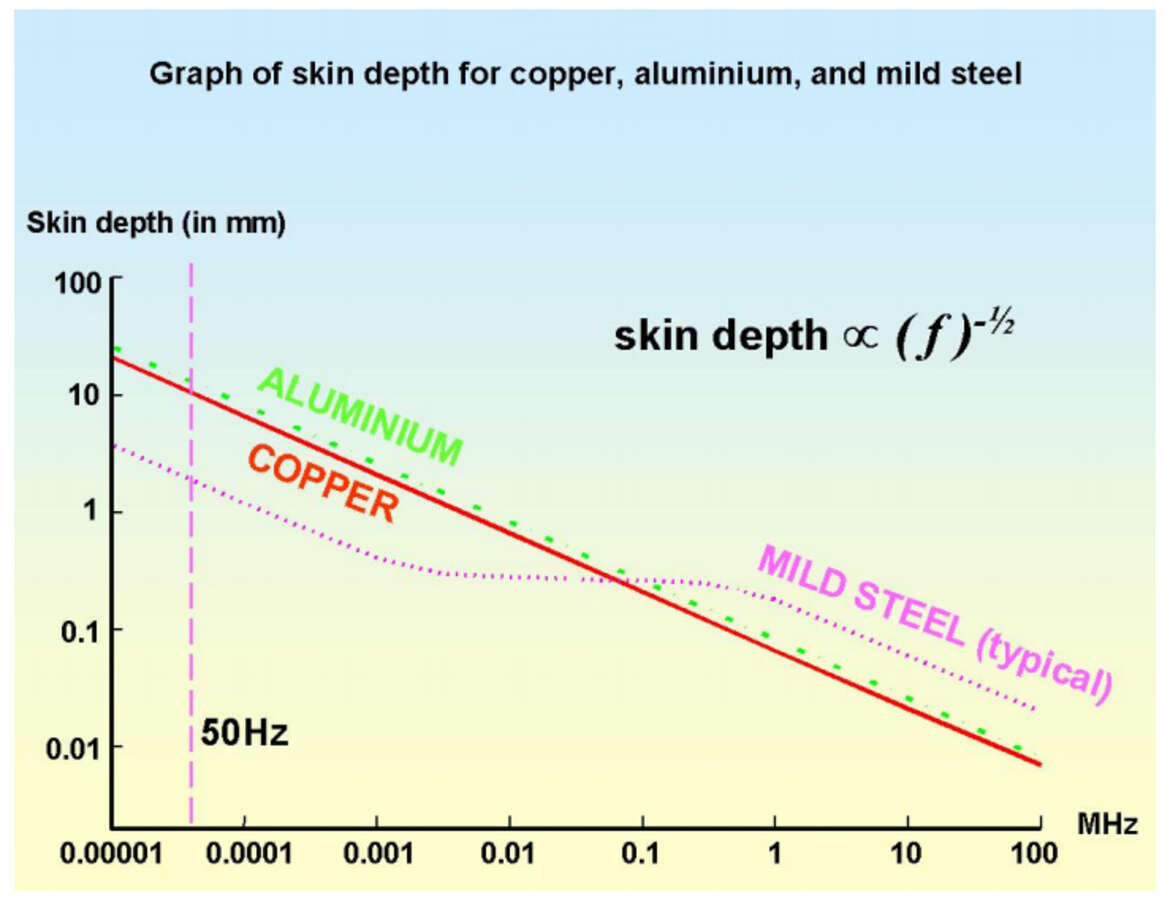
The thickness or depth at which a given material reduces the impinging magnetic field by approximately 9dB is known as the “Skin effect” and is roughly “one skin deep”.
The skin effect is where a current tends to avoid traveling through the center of a solid conductor, limiting itself to conduction near the surface.
For this reason, a material which has a thickness of “3 skins” would have an approximately 27dB lower current on its opposite side and would have an SE of approximately 27dB for that particular magnetic field.
Copper (Cu) and aluminium (Al) have over 5 times the conductivity of mild steel, making them very good at blocking and stopping electric fields, but have a relative permeability of 1 (the same as air).
Permeability in electromagnetism, is the measure of the resistance of a material against the formation of a magnetic field, otherwise known as distributed inductance in transmission line theory.
Typical mild steel has a relative permeability of around 300 at low frequencies, falling to 1 as frequencies increase above 100 kHz, and its higher permeability gives it a reduced skin depth, making reasonable thicknesses of mild steel better than aluminium for shielding low frequencies.
An effective shielding material will have high conductivity, high permeability and sufficient thickness to achieve the required number of skin-depths at the lowest frequency of concern.
For example, 1 mm thick mild steel and pure zinc alloy will be an adequate shielding agent for most cases.
Low-frequency magnetic shielding
Special materials such as Mu-metal, which is an iron-nickel soft ferromagnetic alloy, and Radiometal, again an iron-nickel alloy, have very high relative permeability, often in the region of 10,000.
Due to their notorious fragility, the installation process of these exotic materials must be carefully carried out as even a slight knock might ruin their permeability and then they would have to be re-annealed in a hydrogen atmosphere or discarded.
An additional low-frequency shielding technique is active noise cancelling (ANR). This method is specifically useful for stabilizing the images of the cathode ray tube’s visual display units (VDUs) in environments polluted by high levels of power-frequency magnetic fields.
Waveguides below cutoff
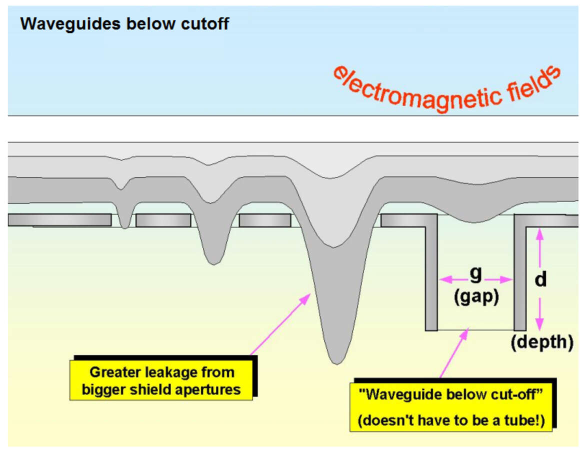
The left part of Fig. 8, shows that the bigger the aperture the greater the EMR leakage. However, the right part of Fig. 8 illustrates that respectable SE can be achieved if the aperture is surrounded with perpendicular to the opening metal walls. This extremely effective method of shielding is known as “waveguide below cutoff” and can maintain the SE of a shield even with 5-10 cm apertures.
A waveguide allows all its impinging fields to pass through, when its internal diagonal (g) is half a wavelength.
Below its cutoff frequency, a waveguide does not leak like an ordinary aperture (as shown on Fig. 8) and can provide a great deal of shielding. The values for adequate SE are approximately 27d/g where d is the distance the EMR wave has to travel through the waveguide before it’s free.
Gasket-dependent design
A gasket is a mechanical seal which fills the space between two or more mating surfaces, generally to prevent leakage from or into the joined objects while under compression.
Even though gaskets are highly effective for rudimentary assemblies, removable panels like doors, hatchets and covers bring an overflow of various problems for all gasket-dependent designs because they must meet a number of conflicting mechanical, electrical, chemical, and in some cases even environmental requirements.
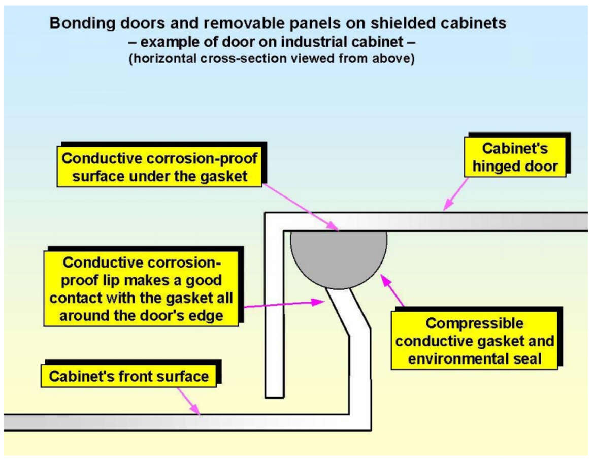
Fig. 9 depicts the design of a typical industrial cabinet and its gasket layout, using spring fingers and a silicone compound or conductive rubber to provide an environmental seal as well as an electromagnetic shield.
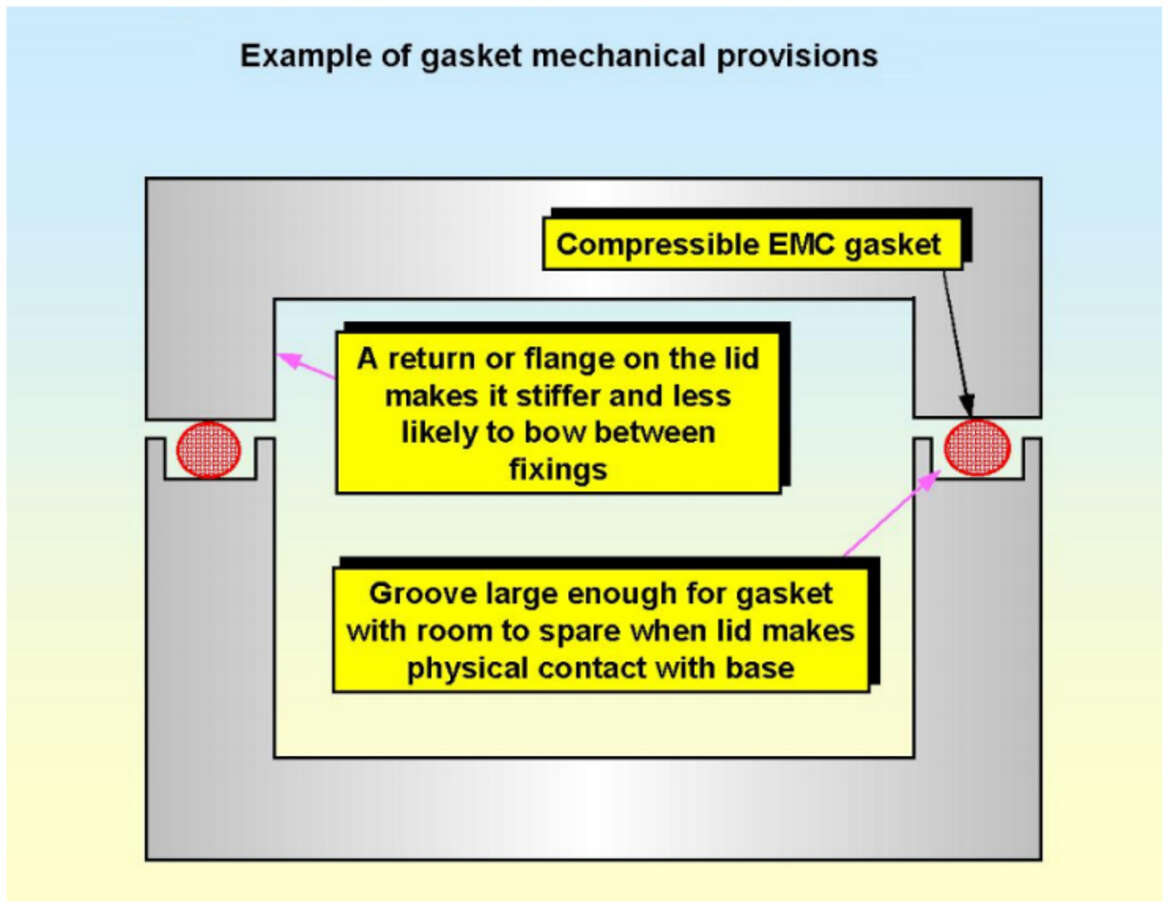
In order for gaskets to be effective, mechanical provisions must be made in order to guarantee easy-to-assemble manufacturing.
Inadequately fitted gaskets, which rely only on large amounts of pressure to generate a tight seal, have a high probability of creating gaps through which EMR can leak.
Unless using a conductive paint, gasket contact areas must not be painted and galvanic corrosion (an electrochemical process in which one metal corrodes preferentially when it is in electrical contact with another, in the presence of an electrolyte). All gasket features, characteristics and details must be accurately illustrated within the manufacturing manual.
Shielding of displays
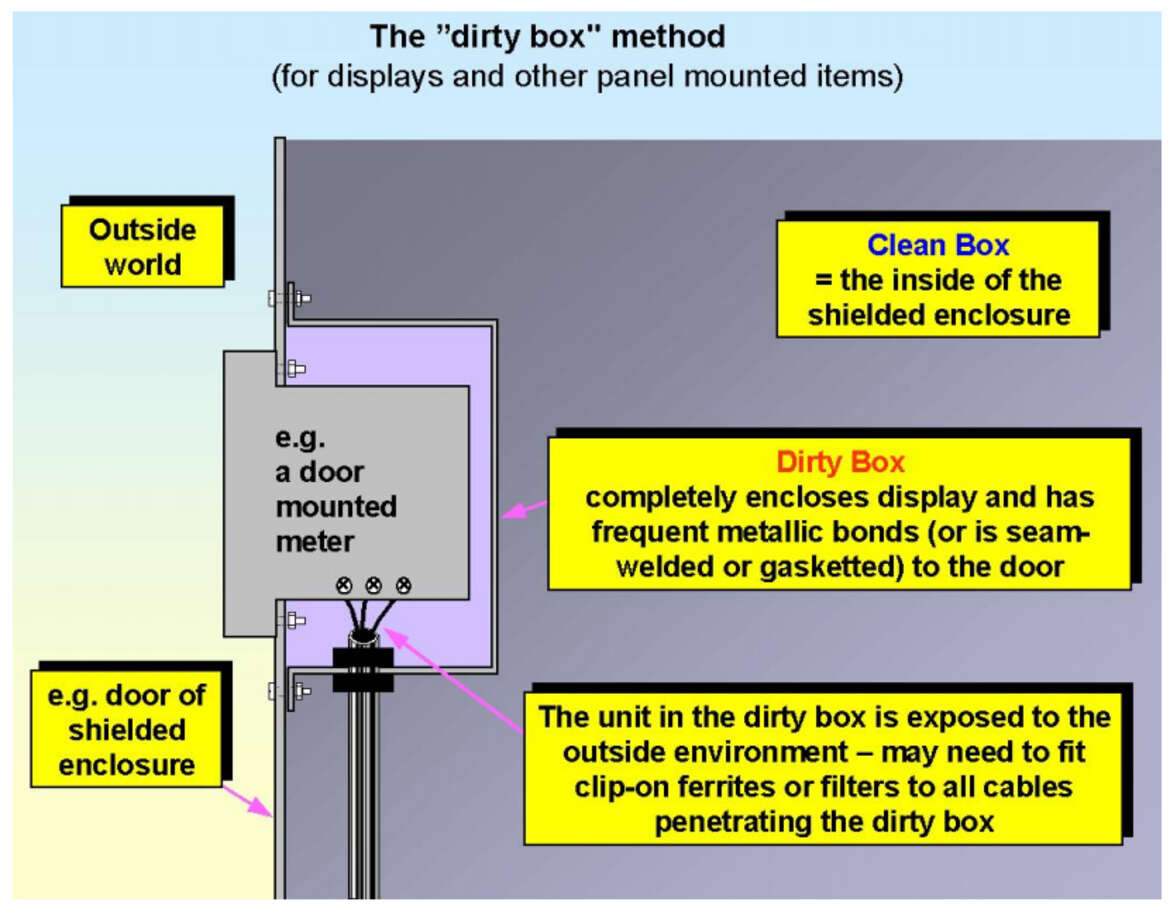
All displays, which are susceptible to a TEMPEST attack, cannot exist in a fully sealed container as they require varying apertures in their enclosures, hence highly compromising the shielding aspect.
Fig. 11 illustrates a visual display units (VDU), such as an automated teller machine (ATM), that uses an internal “dirty box” system to effectively minimalize the EMC field leakage through the aperture. The joint between the dirty box and the inside of the enclosure wall must be treated the same as any other joint in the shield.
Shielding ventilation apertures
Similar to shielding displays, shielding ventilation apertures requires the use of meshes, waveguides below cut off, conductive gaskets or metal-to-metal bonds.
In order to maintain an adequate SE level, the mesh size must be as small as possible. The shield effectiveness of a number of small, identical apertures located near each other is (roughly) proportional to their number, n, (‘SE = 20logn), therefore, two apertures will make the SE worse by 20 x log (2) = 6.02, four apertures 20 x log (4) = 12.04, etc.
For a larger number of small apertures, typical of a ventilation mesh/grille, the mesh size will be considerably smaller than one aperture on its own would need to be for the same SE. At higher frequencies where the size of the ventilation aperture exceeds one-quarter of the wavelength, even this rudimentary and simplistic “20 x log (n)” formula can become unnecessarily complex or inefficient.
Waveguides below cutoff allow high airflow rates with high values of shield effectiveness, and honeycomb metal ventilation shields (consisting of many long narrow hexagonal tubes bonded side-by-side) are best suited for this purpose.
If not designed carefully, the ventilation apertures can start accumulating large amounts of dust and dirt particles, which will further complicate the cleaning process.
Shielding with painted or plated plastics
Plastics enclosure could be stylish and visually appealing but are not an effective shielding agent.
Even though it’s an extremely laborious and technically demanding process, coating the interior of the plastic enclosure with conductive materials such as metal particles in a binder (conductive paint), or with actual metal (plating) could potentially give satisfactory results.
However, most frequently the design of the plastic enclosure does not permit the required SE to be achieved because, as all other enclosures, the weakest points remain the seams (apertures) between the plastic parts, but in this case, they cannot be reinforced with gaskets, thus the inevitable EMR leakage. Therefore, if the plastic enclosure requires shielding, it’s financially vital that consideration is given to achieving the necessary SE right from the start of the initial design process.
Paint or plating on plastic can never be very thick, so the number of skin-depths applied can be quite small. Some innovative coatings, using nickel and other metals, have been recently developed to take advantage of nickel’s reasonably high permeability to reduce skin depth and achieve better SE.
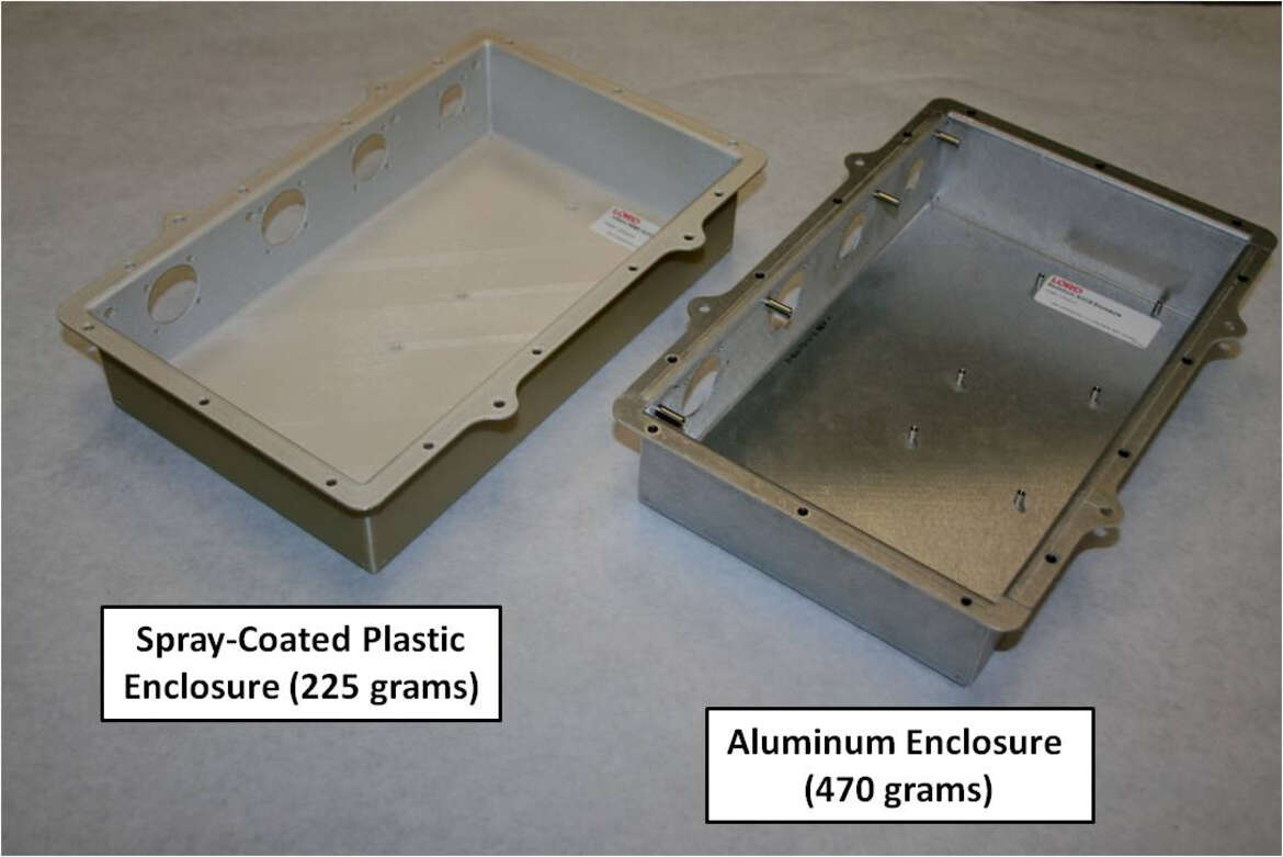
Nonetheless, as shown in Image. 2 the biggest advantage of plastic over the other metals used for shielding, is its light weight.
Shielding without metal
Volume-conductive plastics or resins generally use distributed conductive particles or threads in an insulating binder which provides the mechanical strength. Sometimes these suffer from forming a “skin” of the basic plastic or resin, making it difficult to achieve good radio frequency (RF) bonds without helical inserts (insert made of coiled wire) or similar means. These insulating skins make it difficult to prevent long apertures being created at joints, and also makes it difficult to provide good bonds to the bodies of connectors, glands, and filters. Problems with the consistency of mixing conductive particles and polymer can make enclosures weak in some areas, and lacking in shielding in others.
Materials based on carbon fibers (which are themselves conductive) and self-conductive polymers are starting to become available, but they do not have the high conductivity of metal and so do not give as good SE for a particular thickness.
